Basics of Photoacoustic 3D Imaging Technology
3D Imaging Technology
By using our unique hemispherical detector array (HDA), accurate three-dimensional images can be obtained.
Some other diagnostic devices can produce a pseudo-three-dimensional image by stacking images obtained by mechanically scanning a two-dimensional tomogram, but when the image is enlarged, roughness in the direction of mechanical scanning becomes noticeable.
With our technology, the quality of the image is not easily degraded even when the image is enlarged using an image viewer.
Positioning of photoacoustics
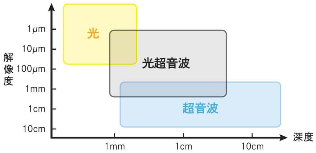
Photoacoustic 3D imaging techniques use a hybrid of light and ultrasound.
OCT (optical coherence tomography) and two-photon excitation microscopy are examples of light-only techniques that provide high resolution but are limited to surfaces with an imaging depth of less than sub-millimeter. (yellow area in the figure).
Ultrasound systems that use only ultrasound can provide high depth but limited resolution.
(light blue area in the figure)
Photoacoustic imaging falls somewhere in between. (Gray area in the figure)
Principle of generation of photoacoustic waves
The principle of photoacoustic wave generation and imaging is as follows
– The specimen (in this case, red blood cells) absorbs light energy
– Converted into thermal energy
– Elastic deformation that expands and recovers is instantaneously generated.
– Elastic waves (longitudinal waves) corresponding to the frequency of ultrasound are generated.
– Ultrasonic waves propagate inside the living body
– Ultrasonic waves are received by an external sensor
– Inverse problem analysis and image reconstruction
Imaging Target
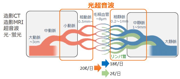
Photoacoustic images visualize blood vessels and lymphatic vessels. It is capable of depicting smaller blood vessels than existing diagnostic equipment.
For blood vessels, light is absorbed by the hemoglobin that consists of red blood cells in the blood, producing photoacoustic waves.
For lymphatic vessels, since lymph fluid is a whitish, non-light-absorbing fluid, dye is taken into the lymphatic vessels from the periphery for imaging.
A typical dye that can be used is indocyanine green (ICG), which is used for medical purposes.
Comparison with other modalities
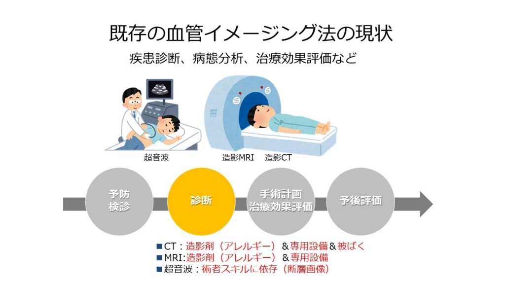


Photoacoustic imaging does not use contrast media, but rather expresses imaging of minute blood vessels better than MRI and CT using existing contrast media. It is noninvasive because it uses a wavelength tunable laser of a strength that does not damage the skin. The technique detects ultrasound waves generated by light irradiation, so measurements can be repeated many times without exposure to radiation.
Furthermore, the system does not require facilities or restricted areas for shielding from radiation or magnetism, as is the case with MRI and CT, making the hurdles to introducing the equipment low.
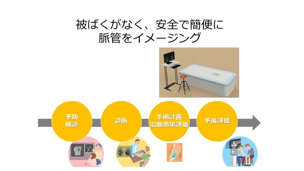
In addition, since the measurement can be performed simply by placing a specimen on the device, imaging is easy, and it is possible to image small animals such as mice as well as large animals including humans, regardless of the size of the specimen.
Features of our photoacoustic 3D imaging system
Three Features
Our photoacoustic 3D imaging system has three features.
Because of the principle of using light and ultrasound, blood vessels can be imaged without contrast or exposure. On the other hand, imaging lymphatic vessels requires the administration of ICG.
By scanning the sensor, images of any size can be obtained. By restricting the area, moving images can also be obtained.
By using our unique hemispheric detector array, three-dimensional images with high spatial resolution can be obtained with high reproducibility.
Adoption of hemispherical detector array (HDA)
The red circle in the above figure represents the sound source, i.e., the sphere where light energy is absorbed by the light absorber.
When the sound source is a single point, sound waves emitted from it propagate isotropically in 360 degrees.
When many sound sources exist as a linear line of points, such as red blood cells in a blood vessel, interference occurs between the waves and they propagate in the orthogonal direction of the line of points.
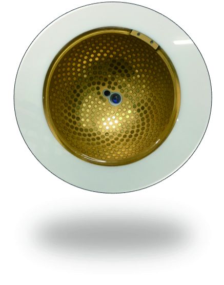
The left figure is a photograph of an HDA, a key device in our photoacoustic 3D imaging technology. The many small circles are ultrasonic sensors that receive ultrasonic waves.
The two black circles in the center are the light-emitting part and the acoustic matching water supply and drainage part.
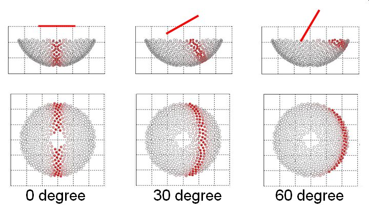
The red bar in the figure above simulates the result. The group of circles depicted below it represents the position of the HDA.
Sound waves generated by the blood vessels in the bars propagate in a direction orthogonal to the blood vessels. The red circles represent the position where the sound waves reach.
When the blood vessel runs horizontally, the acoustic wave propagates through the center of the HDA. If the blood vessel is tilted 30 degrees, the acoustic wave is shifted by that amount; if it is tilted 60 degrees, the acoustic wave is received at the edge of the HDA. If the vessel is perfectly vertical, the acoustic waves will not reach the sensor and no vessel information can be obtained, but the HDA is capable of receiving most vessel runs.
The probes (sensors) of widely used diagnostic ultrasound systems are of the linear type, arranged in a row in the same plane. It is also possible to construct a photoacoustic system by combining this with a laser.
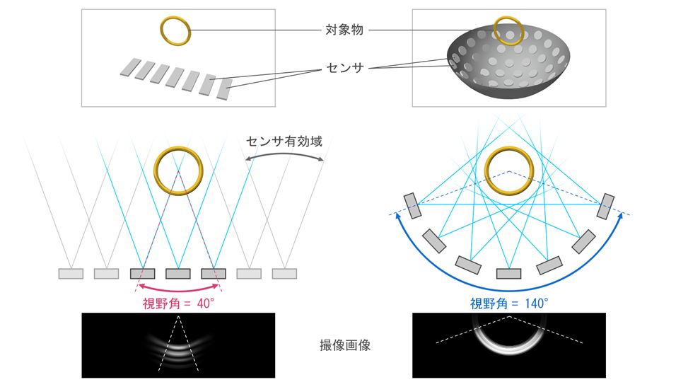
In general, however, each sensor has its own effective range, and the range of reception is approximately ±20 degrees centered on the front of the sensor. The above figure shows the simulation results of receiving sound waves emitted from an assumed ring-shaped optical absorber and reconstructing the image as an imaging image.
While the linear-type receiving sensor cannot reproduce the original shape at all, the HDA can reproduce the three-dimensional structure well.
A linear-type receiver sensor can also be mechanically scanned in a direction orthogonal to the sensor row to obtain a pseudo-three-dimensional image, but the spatial resolution in the direction of the mechanical scanning is degraded. In contrast, our HDA can, in principle, reconstruct nearly isotropic 3D images. These are the key points that enable our device to image the structure of the vascular system in three dimensions.
Adoption of scanning mechanism
A device using an HDA can acquire a good three-dimensional image, but it can only acquire an image of about Φ22 mm at a time. Therefore, we adopted a configuration in which the sensor itself is scanned to acquire images over a wide area. Since the test part (hand) and the sensor are separated by a film, there is no direct contact with the sensor, allowing for safe scanning.
Copyright © 2024 Luxonus | Powered by Luxonus